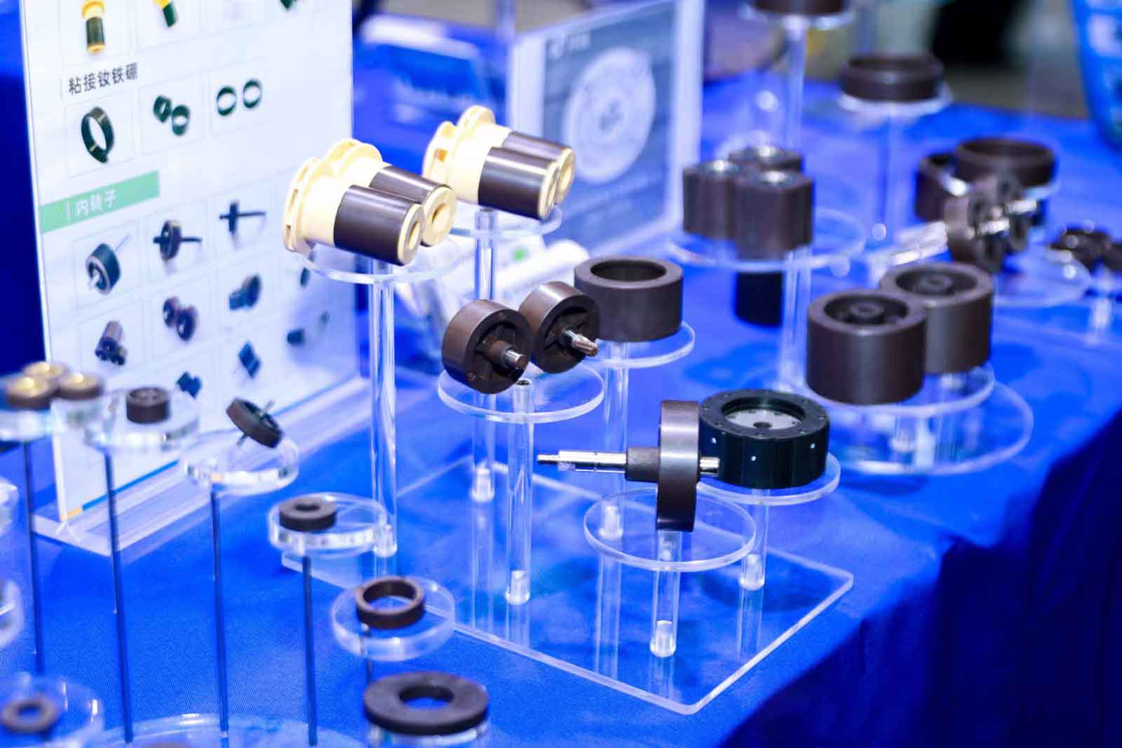
Core Component of Engine Cooling Systems and New Energy Vehicle Thermal Management Systems – Water Pump Rotor
Automotive Water Pump Rotor: Structural Analysis and Technological Evolution
As the core component of engine cooling systems and new energy vehicle thermal management systems, the performance of water pump rotors directly impacts vehicular thermal efficiency and operational stability. The following analysis covers structural, functional, technological evolution, and maintenance perspectives:
I. Functional Principles & Structural Design
The rotor's primary function involves rotating to drive coolant circulation, maintaining optimal temperatures for engines or batteries. In traditional fuel vehicles, mechanical rotors are driven by the crankshaft via a belt, where impeller rotation generates centrifugal force to circulate coolant from the radiator to the engine. New energy vehicle electronic rotors employ brushless motor direct-drive systems with integrated magnets and impellers, achieving precise speed regulation through the Vehicle Control Unit (VCU) to meet varied cooling demands.
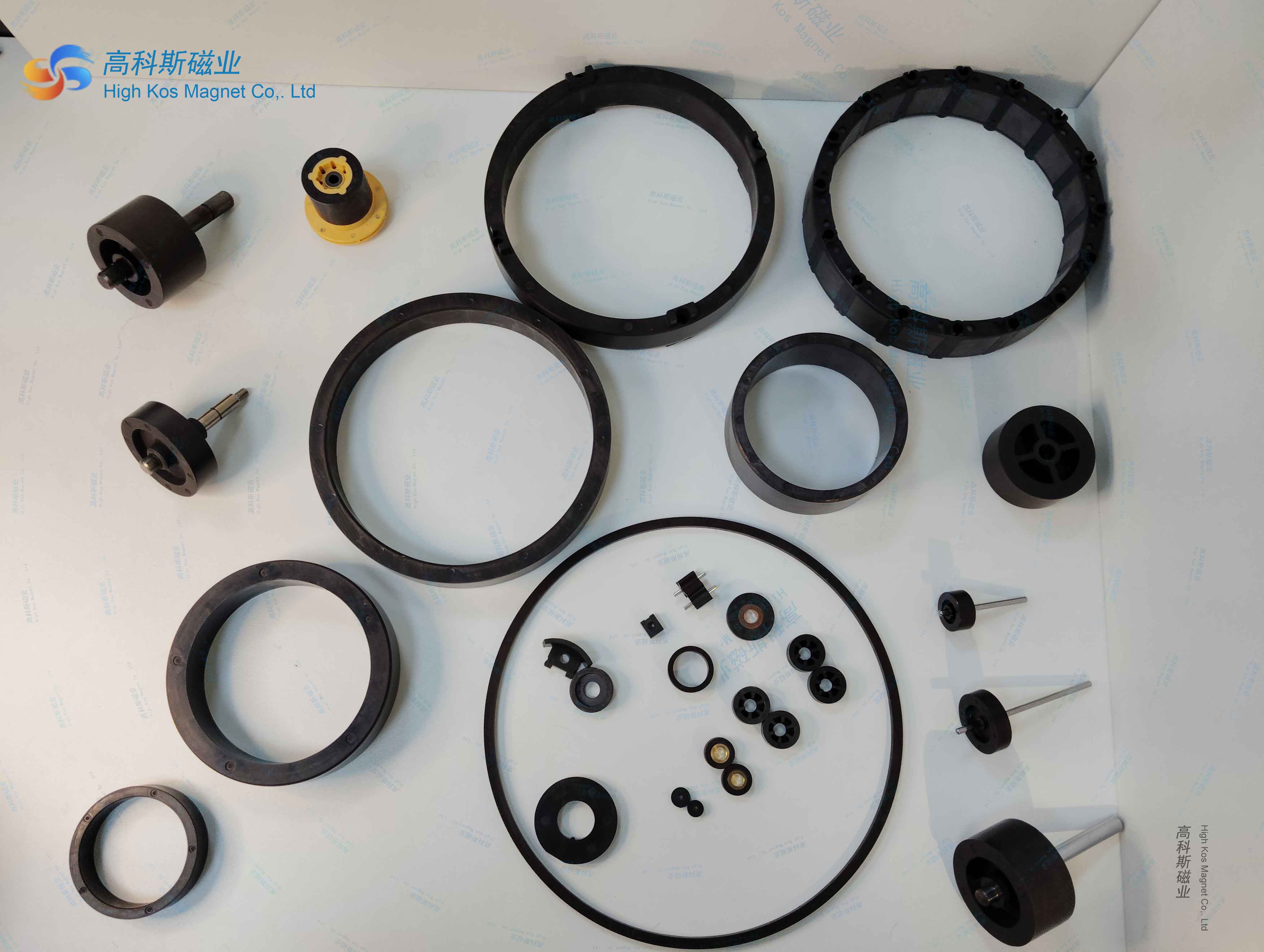
Key structural elements include:
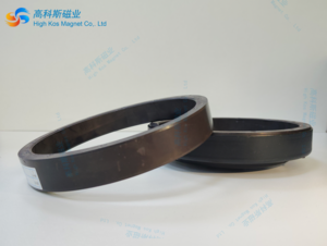
Impeller: Centrifugal design dominates, with blade angle and height determining flow rate and pressure.
Bearings & Seals: Mechanical pumps use grease-lubricated bearings requiring anti-emulsification protection, whereas electronic versions achieve dry-wet separation through magnetic drive, eliminating mechanical seals and leakage risks.
Drive Mechanism: Mechanical types rely on belt transmission, while electronic variants integrate stator-rotor assemblies. For instance, Nidec's C2MTL1 model operates on 12V power with 70-700W output range.
II. Materials & Manufacturing Innovations
Lightweighting: Full aluminum alloy housings reduce weight, while plastic impellers (e.g., PPS materials) balance corrosion resistance and cost efficiency.
Process Advancements: Integrated rotor components manufactured via injection molding attain G6.3 dynamic balancing standards with micron-level runout precision, suitable for high-RPM applications.
Thermal Endurance: Electronic rotors withstand -40°C to 120°C environments, with oil-cooled motor technology enhancing thermal dissipation in specific models.
III. Failure Modes & Maintenance Protocols
Common Failures:
• Impeller wear: Performance degradation from prolonged use or coolant contaminants necessitates scheduled replacement.
• Bearing failures: Mechanical units exhibit abnormal noise from inadequate lubrication or seal failure; electronic versions require PCB thermal management to prevent overheating.
• Control malfunctions: Electronic pump failures stem from solder joint fatigue or waterproofing breaches, diagnosable through PWM signal response monitoring.Maintenance Guidelines:
• Mechanical pumps: Inspect bearing lubrication every 6,000-8,000 km, replace hardened seals promptly.
• Electronic pumps: Clean filters regularly, monitor LIN/CAN bus stability to prevent cold-start failures.
IV. Technological Trends & Market Dynamics
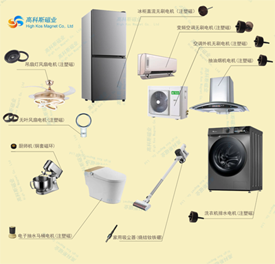
Electrification: Electronic pump adoption exceeds 60% penetration, with hybrid vehicle units valued at RMB 600 and BEVs requiring 2-3 pumps, driving market size toward tens of billions.
Integration: Examples include Shenglong's 3rd-gen tri-function electronic oil pump integrating pump, motor, and controller with CAN FD communication, achieving 30% efficiency gains.
Energy Optimization: Intelligent control algorithms enable demand-based cooling, reducing flow rates by 60% versus mechanical pumps and cutting NEDC fuel consumption by 2%.
Conclusion
The evolution from mechanical drives to intelligent electric propulsion epitomizes automotive energy efficiency innovation. With 800V high-voltage platforms and ultra-fast charging technologies gaining traction, high-power electronic pumps and advanced thermal materials will dominate R&D efforts, advancing thermal management systems toward greater efficiency, acoustic refinement, and durability